 |
 |
The Floppy drive
Q) I'm having intermittent problems in accessing my floppies
Q) My AKAI is reporting that the floppy is not recognized/formatted but it works fine on another machine
Q) Can I replace my AKAI floppy with a normal PC floppy drive?
A) Unfortunately, like all mechanical "friction" devices, the floppy drive tends to fail after some prolongued usage. This is due to the head positioner (corkscrew / Archimedes screw) tolerances and due to dust/oxidization buildup on the heads (especially if you smoke and are in a dusty room or use low quality floppies). Intervening with a isopropyl alcohol and a head cleaner will seldomly help as the tolerances have become so large that the mechanism is not able to "go where it wants to precisely" anymore. If one insits, this can also ruin the data on a previously "healthy" floppy - so do not insist when writing to a floppy if an error occurs. Change floppy disk and try again and read the data back to check it's integrity.
AKAI's floppy standard (you can skip this
paragraph if you're not interested)
Before I venture in explaining what how to
change and set the new floppy, I'd like to mention a few words on why the floppy
unit in the AKAI's are not "PC compatible" out of the box. Many years
ago (around 1971 if I remember correctly) the first 8" floppy units
appeared made by IBM and subsequently made/copied in the east used by the first
machines (not necessarily PCs). This was the beginning of the floppy era
standard, based on serial signals similar to the I2C concept. Infact, all the
lines in your floppy flat cable have a different purpose, each to select or
enable a function like step the motor, enable the writing, check if the floppy
is inserted and see if it is high or low density. The actual data is pulsed on
one single line when written and another line when read from so it is a purely
serial concept design. In these 34 lines that go to your floppy, 18 of them are
ground and 3 are not used. This leaves us with 16 real signal lines. Pins 10,
12, 14 and 16 are the drive select (A/B) and motor select (A/B) lines which
activate and enable Floppy A or B as per standard (each floppy controller was
designed to support a max of 2 drives). If you have noticed, floppy flat cables
have a twist in the last most upper connector where usually floppy A is
connected. The twist involves exactly these lines including their adjacent
grounds (from 10->16 included). What this twist does, is switch drive enable
and motor enable signals so that the last floppy receives these signals switched
around. This is so that, without any "human" intervention, all
floppies can be set the same way from the factory and by simply choosing the
connector one assigns it the drive letter (A or B) as the twist takes care of
switching the signals.
With machines only using 1 drive, it is easier to leave the
cable untwisted instead of wasting time (and money) adding the twist as there is no need to
intervene in the future anyhow. This means that the single floppy on that cable
would be seen as drive B according to this standard - so the floppy drives were set
to be seen as drive A internally. Now as time went by, it became clear that for
PC users the standard was floppy cables with the "twist" as they would
by default have the possibility to add a second floppy. So to "cut the
production costs" floppy drive companies started producing "fixed
set" floppy units around the late 90s without the possibility to be easily
reconfigured. This explains the jumpers on older versions of floppy drives and
why "standard current day" floppy units have none and having been replaced
by simple bridges. However, it is still possible to find user configurable
floppy drives from some manufacturers at request as of course custom made
machines need to be custom configured. Apart from the drive select and motor
enable lines to even complicate your life further, the original floppy units had
also assignable line matrixes and configurable "active high" or
"active low" jumpers. The lines/jumpers that interest us are the "floppy
detect" and "Drive select" ones.
Replacing the AKAI floppy
As you may have understood by now, the AKAI cannot accommodate a standard PC floppy drive "as it is". However, if your floppy drive has jumpers or sliders you can easily move 2 jumpers and you're on track again. If you cannot find a configurable floppy unit, you can try to locate an old 286/386/486 PC which most probably mounts one and replace the "cannibalized" old PC with a new one which you can buy for a few Bucks/Euros. FYI the Amiga 600 or 1200 series also has a correctly set Floppy drive that will work "as is" in the AKAI - then again, you will be left with an Amiga without a working floppy! You cannot use older Amigas as they used Double Density drives (800K) that wouldn't be a good solution with the already little space a 1.44MB floppy can give you for samples. "All this is well" you will probably mumble "but which jumpers must I set to get the damn PC Floppy to work on my AKAI?". Unfortunately it is not so straight forward as it might look - it really depends on what floppy drive you have found with configurable jumpers or sliders.
|
|
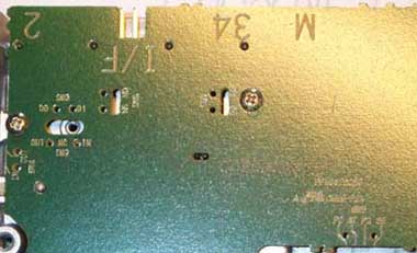
There are so many versions of these that I lost count - I have seen over 50 different floppy pcb layouts in the last 15 years, from the more bulky to the more advanced with less components, some adopting a matrix of pins with jumpers, some sliding switches and some a combination of both. Usually located near the back of the floppy where the connector and power connector is near the step motor, they can also be found underneath the floppy near the edges settable using a pin to slide the switch. Here are 2 pictures just for an example to get an idea of what they look like; the top being a jumper matrix fashion layout and the bottom being a slider switch layout.
The jumpers/sliders to change are 2: one
selects which drive enable line it will use and one selects what line will be
used for floppy detect. The Drive Select jumper is rather easy to find as it is
usually labeled "DS": DS0 (for Drive Select 0) and DS1 (for Drive
select 1) - you must move it from DS1 to DS0.
Now for the trickier part: you have to change the Floppy
Sense or Disk Change to Ready signal. This may be labeled DC/RY. This is a
deviator type jumper or slider (usually 3 pins, 1-2 for one setting and 2-3 for
another) but can also be a 2pin jumper *or* a "rotatable" jumper if
located in a jumper matrix (check 1st pic). This means you need to rotate a
jumper left or right 90 degrees from it's default position around one of it's 2
pins. This simply modifies the pin 34 signal (which is usually Disk Change) and
reassigns it to send the "Ready" signal.
Well that's it. If you manage to reconfigure these 2 settings, you have a perfectly compatible AKAI (and Amiga) floppy unit which you can use again.
One last note: if you don't have any reference on your floppy for this DC/RY jumper, you may discover it by trial and error - I did this many times as it took me less to try the 3 or 4 settings than to understand where the jumpers went and study the pcb. A good hint on knowing that you hit the right jumper is that when you move it your AKAI shouldn't report a "floppy not ready" or similar error when you have a floppy inserted. Infact line 34, which the AKAI interprets as the Ready Signal is (before the re-configuration) the Disk Change signal. As they behave with inverted logical values (one is active low the other active high) if you leave no disk in the drive, the AKAI will think that the drive is ready and try to read from it! So this will give you some feedback on the jumper you are toggling or moving if it stops doing that (you may have hit the jackpot).
Good luck.